

Professional Sterilization Monitoring Supplier | Regular Industry Knowledge Sharing
Resolve Common Faults, Zero-distance Sterilization Safety!

-
 Common UV problems
1、 Voltage meter not displaying/voltage meter malfunction
Troubleshooting Guide:
1. Open the computer case, check the wiring terminals and connectors of the voltmeter, and troubleshoot any loose, disconnected, or disconnected circuits.
2. Use a multimeter to measure the corresponding wiring terminals and check if the input voltage is normal.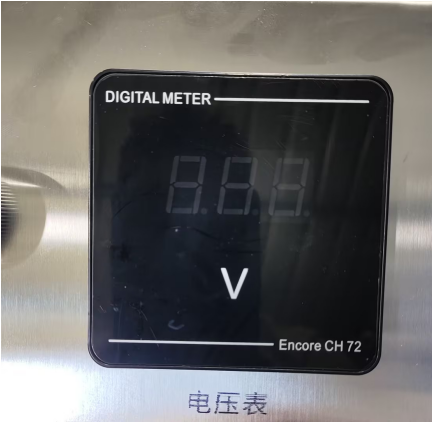
2、 Indicator light/tube malfunction
Troubleshooting Guide:
Firstly, visually observe the working status of the lamp tube and indicator light, and classify and troubleshoot according to different fault phenomena:
Scenario 1: All light tubes are lit up normally, only the indicator light is not on
Using the line swapping method to investigate:
If indicator light 1 does not light up and indicator light 2 lights up normally, swap and connect the indicator light circuits of the two ballasts.
-After swapping, if the original indicator light still does not light up: it is determined that the indicator light itself is damaged;
-After adjustment, if the original non illuminating indicator light returns to light up and the original normal indicator light goes out, it is determined to be a ballast fault.
Scenario 2: Some lamps are lit up, while others are not lit up
Using the same circuit swapping method for troubleshooting:
If Lamp 1 does not light up and Lamp 2 is working properly, swap and connect the power supply lines of the two ballast lamps.
-After swapping, if the original non illuminating lamp still cannot light up: it is determined that the lamp body is damaged;
-After adjustment, if the original unlit lamp tube lights up normally and the original lit lamp tube goes out, it is determined to be a ballast fault.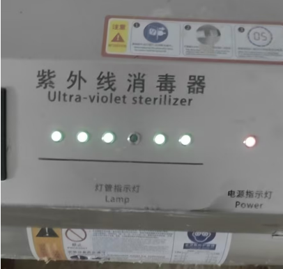
3、 Button switch malfunction
1. Open the chassis shell, check the button switch wiring terminals, and investigate poor contact issues such as circuit detachment, looseness, and virtual connections.
2. Check if the fixed base of the button switch is loose or displaced, causing the button to fail to trigger properly.
3. Check for oxidation, aging, or damage to the internal contacts of the switch, which may cause button failure. -
Common problems in water quality monitoring
1、 Turbidity leakage
1. First, adjust the water intake of the device, remove the cover of the turbidity sensor, and check whether there are any foreign objects blocking or accumulating in the internal pipelines and probe positions.
2. Check the drainage and outlet pipelines one by one, and investigate problems such as pipe bends, debris blockages, and poor drainage.
3. Adjust the installation angle and height of the overflow outlet to ensure that the outlet is vertically downward and the overall position is lower than the turbidity, avoiding backflow and overflow leakage.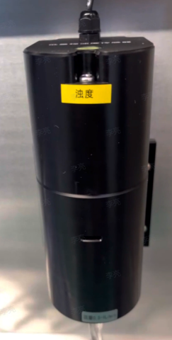
2、 The residual chlorine data is inaccurate
solution
Remove the residual chlorine sensor from the circulation channel; Add about 1000mL of purified water to the beaker, then add an appropriate amount of sodium hypochlorite solution (or 84 disinfectant containing hypochlorous acid) dropwise and stir well.
Use a handheld DPD colorimeter to measure the actual residual chlorine value of the water sample. After the value stabilizes, place the residual chlorine sensor in the water sample and gently shake it for comparison:
1. If the difference between the two is ≤ 0.1mg/L, it is judged that the sensor is normal;
2. The numerical deviation is significant. Contact technical personnel and use USB-485 data cable to remotely calibrate the sensor through a computer;
3. Enter the device numerical setting interface, enter the password, find the residual chlorine parameter item, and manually add compensation value correction data.3、 The turbidity value is inaccurate
1. Remove the fixing screws of the turbidity sensor and disconnect the connecting pipeline.
2. Remove the top laser turbidity probe.
3. Gently wipe the laser emitting component with a glasses cloth, while rinsing and cleaning the inner wall of the flow channel to remove dirt and attachments.
4. After cleaning, reset and fix the sensor, connect the pipeline, run with water, and observe whether the turbidity reading returns to normal.
If the numerical deviation is still significant, it is necessary to check whether the water body contains bubbles and take timely defoaming measures.Notes:
The conventional service life of sensors is about one year, depending on the water quality and environment.
If poor water quality such as sewage, surface water, and river water is monitored for a long time, it will accelerate component wear and shorten the service life.
After long-term operation of the equipment, if there are malfunctions such as inaccurate data and communication abnormalities, it needs to be returned to the factory for inspection and maintenance, and the sensors should be maintained or replaced according to the actual situation. -
Common problems with ozone generators
1、 Ozone generator melting, burning, odorless
When the equipment has no ozone odor, priority should be given to checking the power supply status to confirm whether the voltage is normal and stable. When the ozone generator is working, it is in a charged state. It is strictly prohibited to touch the body with electricity to avoid the risk of electric shock. The default automatic operation period of the device's factory control switch is from 23:00 to 23:30 every day, with a single disinfection time of 30 minutes. Do not manually turn on the device for a long time, as continuous overload operation can cause overheating of the body, component melting, and permanent damage to the ozone generator. Multiple sets of timing can be set, adopting a short-term multiple operation mode to avoid prolonged continuous operation of the equipment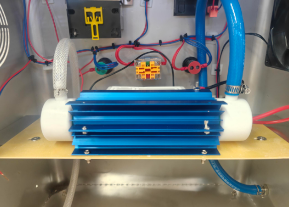
2、 Time control switch E1/E2 malfunction
E1- No start time set
E2- End time not set
Please verify the parameters of the time control switch and confirm that the start and stop time settings are correct. It is recommended to check and troubleshoot multiple sets of timing programs one by one.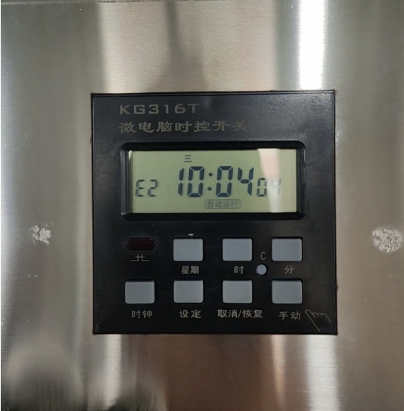
3、 No airflow at the device outlet
Equipment gas path process: compressor gas supply → ozone generator → equipment outlet
1. Open the back cover of the computer case and focus on checking the internal air outlet pipeline to identify any issues of pipeline detachment, looseness, damage, or air leakage
2. Observe the operating status of the compressor, confirm whether the compressor starts and runs normally, and determine whether the air supply is normal.
Provide high-quality product solutions and one-stop comprehensive after-sales services for customers
After-sales Consultation